
[ad_1]

Right here is an easy FM Radio utilizing an IC1 1260.This IC is a 16-pins. All of the elements used for this FM radio may be simply bought in a market or may be taken away out of your outdated Black & White TV set, radio e.t.c.
Most of FM radios work on 10.7MHz IF frequency however this on works on 5.5 MHz IF frequency. As a ten.7MHz IFT coils is tough to seek out in a market we used right here 5.5MHz IFT coil which may be simply discover in a market and in addition may be taken away out of your outdated Black & White TV units. Additionally 5.5MHz 3-pin ceramic filter used for this FM radio may also be simply discover in a market.
Circuit and Working
The guts of this circuit is a transistor Q1 (BF494) and IC1 (LA1260) and utilizing few resistors and capacitors, 5.5MHz ceramic filter and 5.5 MHz IFT coil.
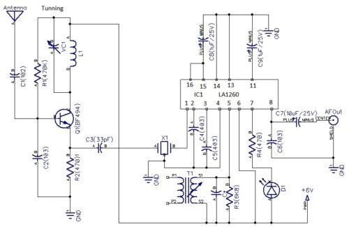
Transistor Q1 (BF 494) along with coil L1 (5 turns of 23 SWG wires of 5mm air core), trimmer capacitor VC1 (2-22pF), resistors R1 (470K), R2 (470) and a capacitor C1 (102), C2 (103), C10 (10pF) makes an oscillator of frequencies of 93.5MHz-113.5 MHz. A 88.00MHz-108MHz enter sign type an antenna( 75cm) and to a base of a transistor Q1(BF 494) via a capacitor C1 is combined with 93.5MHz-113.5MHz oscillator and a 5.5 MHz IF frequency is taken away from a capacitor C3(33pF) and is related to a pin 1 of 5.5MHz ceramic filter.
Subsequent join a pin 2 of X1 to a floor and pin 3 to a pin no: 1 of LA1260. Pin 2, pin 3 of IC1 are additionally related floor with a capacitors C4, C4 (403). Pin 4 is related to floor. Pin 5 is related to +6V with a resistor R3 (6K8), pin 6 is related +6V, pin 7 is related to +6V via a D1 and R4.An AF output is taken away from a pin 8 of IC1 via an electrolytic capacitor C7 (10uF/25V). Capacitor C6 (103) is grounded. Pin 11 of IC1 is related to floor with an electrolytic capacitor C9 (1uF/25V). Pin 13, 14 are floor. Pins 15, 16 are related collectively and are related to C8 (1uF/25V).
Development and Testing
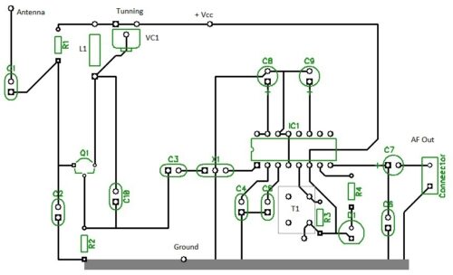
A vero board of dimension 5cm*7cm is appropriate to your venture. You too can construct this on a PCB board given on an article. An inductor coil L1 may be made by winding 5 turns of 23 SWG wire on 5mm air core. You’ll want a 16-pin IC socket to your venture. Place 16-pin IC socket on a center of a veroboard. Place all of the elements on a veroboard as given on a circuit diagram and solder all of the elements on a vero board or on a PCB board.
Now we are going to take a look at your FM radio. Join an influence provide of +6Volts to your FM radio. Join an AF output out of your FM radio to an AF amplifier. Activate an AF amplifier and set a quantity of AF amplifier to mid place. You’ll hear a hissing sound from a speaker of an AF amplifier.
Now could be your FM radio is working and prepared for utilizing. Join a 75cm lengthy wire and connect with your FM radio. Take a small plastic screwdriver and gently tune VC1 till you’ll hear a station.
Additionally tune a 5.5 MHz IFT coil till you’ll hear clear and loud sign. You’ll see a LED1 glowing as quickly as a sign is acquired.
So, your’ FM radio utilizing LA1260 is working and prepared for a utilizing.*
Elements- Checklist
Semiconductors
Q1: 494
IC1: LA1260
Resistors
R1: 470K
R2: 470
R3: (6K8)
R4: (470)
Capacitors
C1: 102
C2: (103)
C3: ( 33pF)
C4, C5: (403)
C6: ( 103)
C7: 10uF/25V
C8, C9: ( 1uF/25V)
Miscellaneous
X1(3-pin 5.5MHz Ceramic Filter), T1 (5.5 MHz IFT coil, 16-pin IC socket, 5cm*7cm vero board, VC1, 6Volts battery, wires.
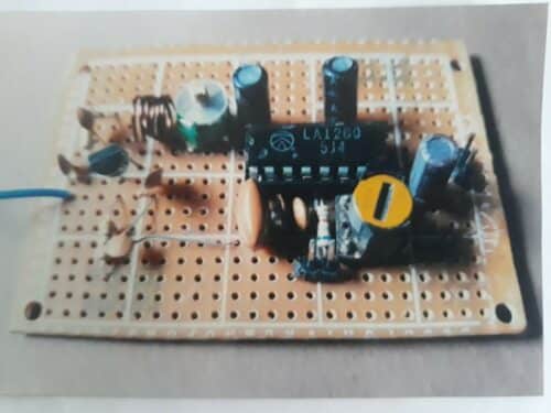
Writer Prototype
[ad_2]