
[ad_1]
We designed a Quiz Buzzer circuit that can be utilized for eight gamers/groups in quiz competitions organized by colleges or schools.
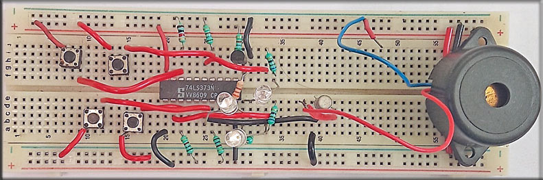
Usually, quiz circuits are designed with microcontrollers, however this easy circuit doesn’t use any microcontroller. The center of this circuit is a precedence encoder, 74LS373. The creator’s prototype constructed on a breadboard is proven in Fig. 1.
Parts Required
| Components Listing | |
| Semiconductors: | |
| IC1 | -LM7805, 5V voltage regulator |
| IC2 | -74LS373 precedence encoder |
| T1, T2 | -2N2219 NPN transistors |
| BR1 | -1A bridge rectifier |
| LED1-LED9 | -5mm LEDs |
| Resistors (all 1/4-watt, ±5% carbon): | |
| R1 | -1-kilo-ohm |
| R2-R10 | -5.6-kilo-ohm |
| R11-R18 | -100-ohm |
| Capacitors: | |
| C1 | – 1000μF, 35V electrolytic |
| Miscellaneous: | |
| CON1 | – 2-pin connector |
| S1-S8 | – Push-to-on switches |
| X1 | – 230V AC main to 9V, G39 500mA secondary transformer |
Quiz Buzzer Circuit
Fig. 2 exhibits the circuit diagram for the quiz competitors buzzer.
WHERE IS THE REST OF THIS ARTICLE’S CONTENT?
[ad_2]